 |
| Place of Origin: | China |
| Brand Name: | YUYANG |
| Certification: | BS 476 (20-23) – BS EN 1363 (1-2) – BS EN 1364 (1) – BS EN 1365 (1) BS EN 1366 (1-3) - BS EN 1634-1 – ASTM E 119 – ASTM E 814 - UL10 (B-C) - UL 263 – UL 1709 - UL10 (B-C) – UL 1479 – UL 2079 -- ISO 834 (1, 4, 8) - ISO 3008 – ISO 3009 |
| Minimum Order Quantity: | 1 set |
|---|---|
| Price: | Negotiation |
| Packaging Details: | Plywood Box |
| Delivery Time: | 35~40 work days |
| Payment Terms: | T/T, L/C, Western Union |
| Supply Ability: | 2 sets per quarter |
| Model Number: | Vertical Fire Resistance Test Furnace | Power: | Electronic |
|---|---|---|---|
| Product Name: | Fire Testing Equipment | Usage: | Fire Resistance Test For Construction Products |
| ASTM Standards: | ASTM E 119 – ASTM E 814 | BS EN Standards: | BS 476 (20-23) – BS EN 1363 (1-2) – BS EN 1364 (1) – BS EN 1365 (1) BS EN 1366 (1-3) - BS EN 1634-1 |
| UL Standards: | UL10 (B-C) - UL 263 – UL 1709 - UL10 (B-C) – UL 1479 – UL 2079 | ISO Standards: | ISO 834 (1, 4, 8) - ISO 3008 – ISO 3009 |
| High Light: | flame test equipment,flammability test apparatus |
||
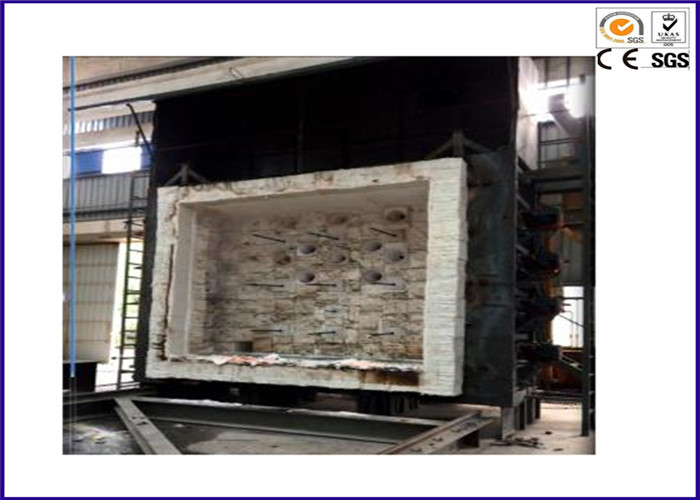
ASTM E119 ISO 834 Large Scale Vertical Fire Resistance Flammability Testing Equipment
GENERAL DESCRIPTION
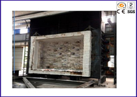
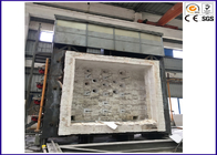
Full Scale Vertical Fire Resistance Test Furnace designed to employ liquid or gaseous fuels and is capable of heating of vertical separating elements on one face
The furnace linings consist of refractory materials with densities of less than 1000 kg/m3and these constitute more than 70% of the internally exposed surface of the furnace.
The furnace is custom built to provide the fire exposure conditions with respect to thermal exposure and pressure and comply to the requirements of CEN, ISO and IMO standards.
The minimum internal chamber dimension measures 4000 mm wide x 3000 mm high x 1000 mm deep.
This full scale fire resistance test furnace will be built at the factory in modular units and shipped in 40ft HC containers. On arrival, the modular units will be assembled on a strong foundation prepared by the customer.
Furnace Steel Casing
The furnace casing will be made of structural steel sections and plates designed for robust usage. The steel plates are reinforced with steel C-Channels, I-beams and steel sections to counter structural distortion due to heat, especially to areas where holes are provided on the casing for burners, thermocouples, pressure probes, viewing ports.
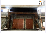
Cast iron plates are bolted to the front outer face of the furnace to provide a strong surface to mount the test specimen restraint frame.
Four sets of self-locking roller clamps are installed to allow the test specimen restraint frame to securely hold onto the front of the furnace.
Furnace insulation
The furnace refractory lining is comprised of insulating firebricks rated at 1430°C with a density of 900 kg/m3 on the hot face and backed by fibreboard insulation on the cold face. At a temperature of 1200 °C, the furnace outer casing temperature will not be higher than 75 °C, two hours into the fire test.
High temperature precast blocks made of fibre-reinforced refractory castable rated at 1600 °C will be installed along the perimeter of the furnace opening to provide a protective surface to withstand constant abrasion of the test specimen frame that is mounted on the furnace.
Four sets of viewing ports will be placed at the furnace back wall to allow operators to have a complete view of the test specimen during the fire test. The viewing port assembly is made of clear quartz glass plate, housed with an air-cooled enclosure and insulated to prevent heat loss.
The furnace exhaust opening and flue gas off-take containing the damper will be lined with low thermal mass ceramic fibre insulation with a density of 128 kg/m3.
All refractory materials used for the furnace will be able to withstand cyclical heating and cooling
Painting
The outer furnace casing will be painted with silver colour high temperature paint.
Pressure Control System
Three motorized heat resisting steel dampers will be built into the extract flue to enable overall control of the pressure within the furnace chamber. Adjustable extract ports will also be provided to enable the extraction rate to be varied at different positions within the furnace chamber. The motorized steel dampers will be capable of adjustment from the designated control room via the Fire Test Data Management System.
Combustion System
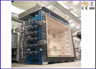
Twelve premixed LPG / Natural Gas burner will be supplied in which, 6 units will be installed on the left hand side of the furnace wall measuring 3 metres x 1.3 metres and the other 6 on the right hand side.
The combustion equipment will consist of :
12 – Gas Nozzle Mixing Burners
12 – Air Balance Control Valves
12 – Gas Balance Control Valves
12 – Pilot Gas Regulators
12 – Gas Shut-Off Valves to burners
12 – Fully automatic Gas Burner Safety Control
12 – Spark ignition, transformer and cable
12 – Ultraviolet scanner
12 – Flexible Air Pipes
12 – Flexible Gas Pipes
12 – Manual Air Butterfly Valves
3 – Main Gas Shut Off Valves
6 – Gas Pressure Switches with connectors
30 – Gas Manometers
3 -- Air Gas Micro ratio Valves
3 -- Combustion Air Blower
3 -- Main Gas Filter
3 -- Main Gas Regulator
The burners will be suitable for use with Natural or Liquefied Petroleum gas (to be confirmed by customer at the time of order)
All burners will be equipped with standard safety features, including those detailed above, and will comply with local gas safety regulations.
The burner blocks will be manufactured from castable material comprising nominally 80% alumina and will be able to withstand the regular thermal shock associated with conducting this type of test.
Gas and Air Distribution System
Three air blowing fans will be provided to supply air to the furnace combustion system and to oxygenate the furnace atmosphere to meet the fire test standard requirement pertaining to minimum oxygen level.
The fans will be operated from the combustion control panel in the furnace control room.
All interconnecting air pipework will be pre-fabricated in the factory for ease of handling and connected on site. The fans will be supplied with isolating dampers.
Prior to fabrication, the routing of all internal gas piping with connection to the main gas shut off valve will be discussed with the customer to match the layout of the laboratory building . The main shut off valve will be supplied and connected to the gas supply system.
The gas and air distribution system will comply with all safety requirements in the country. All gas and air piping will be painted in internationally agreed identification colours.
Extraction System and Chimney
An extraction system will be provided and will include an extract fan and flue ducting to control the evacuation rate of hot combustion gases from the furnace to the chimney during a test.
The extraction fan will be activated from the control room, from a switch that can be set on automatic or manual operation mode.
All exhaust gas ducting between the extract fan and the furnace will be constructed from prefabricated steel sections and assembled on site. The ducting will be insulated to withstand regular heating and cooling cycles typical of batch firing type, fire resistance tests. The external surface of the ducting will be painted with high temperature paint for protection against corrosion.
A draft inducer will be supplied to dilute the exhaust gases to reduce the temperature of the gases passing into the extract fan to below that of the operating temperature of the fan. This low temperature exhaust gas will then be evacuated into the chimney.
A chimney having an internal diameter of 950mm and a minimum height of 3 metres above the highest point of the roof can be supplied, if requested by the customer, or we can supply the drawings to the customer to enable him to construct this himself on site. This chimney shall be made from mild steel. Designed to be free-standing, customer have to prepare a foundation that has been designed for overturning due to wind load and soil settlement. To prevent scorching or injury to laboratory staff, the chimney will be insulated up to 3 metres height.
The quotation for the design and fabrication of the chimney and ducting can be provided once information on the laboratory building is available.
Platform / Walkway
A complete platform / walkway will be supplied which will be designed to allow safe and convenient access to the viewing ports and to all instrumentation positioned at the sides and rear of the furnace. The assembly will be provided with appropriate handrails and kickplates to ensure safe use by operators and clients. The surface of the walkway will include provision for minimizing slipping of personnel using it.
Plate Thermometers
Nine plate thermometers, as specified in the relevant CEN standards will be provided and will be equally spaced over the plane of the exposed area of the specimen. The positions of the thermometers in the furnace will satisfy the requirements of the relevant CEN standards. The thermometers will be capable of being connected to the computerized data acquisition and data handling system to enable monitoring and recording of the furnace temperature before and during tests.
Furnace Thermocouples
Nine furnace thermocouples having the specification given in the relevant IMO test method, will be provided. Provision will be made to locate them in the required positions through the rear wall of the furnace. They will be protected by appropriate heat resistant tubing to minimize distortion during tests. The thermocouples will be connected to the computerized data acquisition and data handling system to enable monitoring and recording of the furnace temperature before and during tests.
Instrumentation Connection Boxes
An instrumentation connection box will be provided in a convenient location close to the furnace, the location being shielded from heat from the furnace, to enable all instrumentation to be connected with minimum effort. The box will contain individually numbered connections which are linked by multi-core to correspondingly numbered connections in the designated control room which in turn will be connected to the computerized data acquisition and data handling system to enable monitoring and recording of the instrumentation before, during and after tests.
Ambient Temperature Thermometer
An ambient temperature thermometer for monitoring and recording the ambient temperature of the laboratory prior to and during tests will be provided and will be connected to the computerized data acquisition and data handling system to enable monitoring and recording of the temperature before and during tests.
Pressure Transducers
Two pressure transducers will be provided and will be located in appropriate positions to satisfy the requirements of the relevant Standards. The transducers will be moveable between positions, if required, and will be connected to the computerized data acquisition and data handling system to enable monitoring and recording of the outputs at pre-determined intervals.
Oxygen Analyser Tapping Points
Provision will be made on the furnace for sampling and measuring the oxygen concentration at regular intervals during the fire resistance test.
A permanent sampling line with connection will be provided to enable an oxygen analyser to be connected to sample the furnace gases and the signal generated from the analyser to be recorded in the fire test data management system and displayed on the monitor screen
Deformation Measuring Device
A portable laser device for measuring the deflection of specimens from their original position at their centre will be provided and it will comply with the requirements of the relevant CEN standards.
Timing Device
A timing device having a large display which can be easily seen by testing staff during a test and is clearly visible on photographs of the specimen during the test, will be supplied. The device will be linked to the Fire Resistance Test Data Management System to ensure that it starts at the same time as the control system. The device will be capable of displaying elapsed time to the nearest second and accurate to within 1 second in one hour.
![]()
![]()
Contact Person: Yannis Ye
Tel: +86-13825723571